SULFATE REMOVAL SYSTEM
Removing Sulfate from brine in Chlor-Alkali plants
Sulfate is always present in various concentration in salts used for chlorine production. It is recycled with the depleted brine, and builds up in the brine loop. Following the specifications for most modern electrolyzers and membranes manufacturers, the concentration of sulfate in the feed brine to the electrolyzer should be limited to 6~8 g/l.
When the concentration of sulfate is too high, oxygen is released at the anode which reduces the current efficiency of the chlorine production process, and affects the marketability of the chlorine. At even higher concentrations, sulfate forms harmful deposits on the membranes and damages the anodes coating.
Barium salts, traditionally used to precipitate sulfates in brine, are costly and toxic. The disposal of the precipitates is becoming an environmental and regulatory issue.
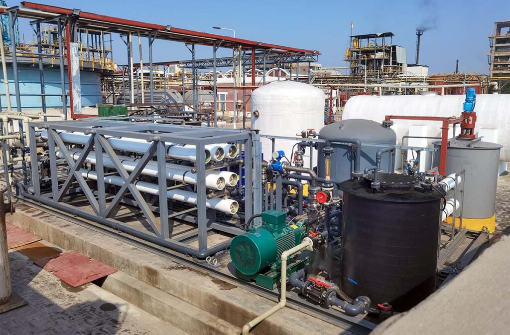
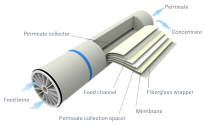
Semi-permeable membranes are the ideal modern solution to remove sulfate from brine. A fraction of the depleted brine is diverted to the sulfate removal unit, where it is passed along selective membranes in a cross-flow configuration. The membranes retain the divalent sulfate ions and allow monovalent sodium and chloride to pass through. The residual brine containing a high concentration of sulfate, usually between 80 g/l and 100 g/l, can be beneficiated by further separation of pure sodium sulfate which can be crystallized and sold as a commercial product.
The permeate, with a concentration of sulfate of less than 1 g/l is sent to the saturator.
The amount of sulfate removed by the SRS must balance out the sulfate brought into the system as impurity in the salt, and as sodium sulfite used for dechlorination. An ample operational margin is usually added to cater for an initial spike of sulfate concentration in the brine, and allow the system to shut down for short periods without affecting the operation of the chlor-alkali section.
Benefits
Innovative
In chlorine plants, nano-filtration substitutes for the traditional sulfate removal methods such as barium precipitation or brine purging.
In chlorine plants, nano-filtration substitutes for the traditional sulfate removal methods such as barium precipitation or brine purging.
Strong Cost Reductions
Considerable operating cost reductions, through complete elimination of the barium precipitation chemicals (saving up to 1 million USD per year), improved electrolyzer power efficiency, extended life of the membranes and of the anodes coating, and recovery of valuable salt that would otherwise be purged.
Considerable operating cost reductions, through complete elimination of the barium precipitation chemicals (saving up to 1 million USD per year), improved electrolyzer power efficiency, extended life of the membranes and of the anodes coating, and recovery of valuable salt that would otherwise be purged.
Reduce waste
Environmental benefits through reduced effluent volumes or elimination of the barium sulfate disposal issue.
Environmental benefits through reduced effluent volumes or elimination of the barium sulfate disposal issue.
Additional profit
Optional beneficiation of sodium sulfate as a commercial by-product.
Optional beneficiation of sodium sulfate as a commercial by-product.
Features
Nano-filtration membranes are made from a permeable film of polysulfone, coated with a molecular film of a particular polyamide that is impervious to bivalent ions.
Membranes do not need to be backwashed. A rare acid cleaning is needed to remove silica, at a frequency depending on the silica content of the brine.
The average membrane life is three years.
Process
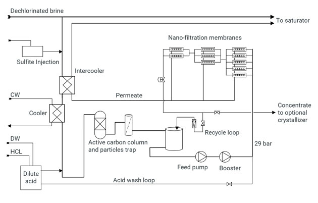
The nano-filtration membranes are far more sensitive to active chlorine than other components of the brine loop. Hence, incoming brine is first dechlorinated by injection of sodium sulfite.
The brine is then cooled in titanium heat exchangers and an intercooler.
The pH is adjusted to slightly acidic.
A final barrier for active chlorine consists of an activated carbon column.
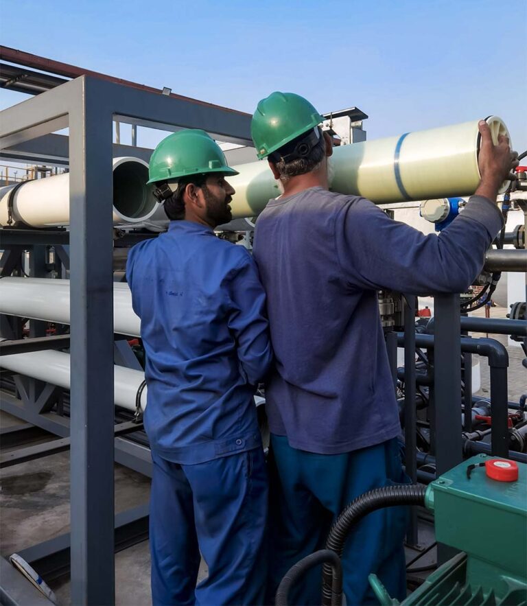
It is then pumped to a pressure of nearly 30 bar, and passed through the train of membranes.
The permeate is re-heated to recover the heat of the incoming brine, and returned to the saturator.
Our SRS systems are entirely self-controlled by PLC’s, and may be connected to your DCS for displaying information.
Our design philosophy
Our turn-key projects and components are designed in Europe and built with the best available local resources. Our design philosophy is to always seek for a “lean design” with the smallest number of components and the smallest number of connections to reduce maintenance, reduce the chances of failures, and reduce leakages. We strive to offer the best quality at the best price.
How to plan for SRS
Calculate your hourly input rate of sulfate in salt. This is the key target for your SRS sytem. This amount of sulfate must be removed, on average.
Remember that it is easier to remove sulfate from a sulfate rich brine than from a lean brine. Unfortunately, the SRS cannot operate on the saturated brine, because salt crystals would form on the nano-membranes and block it. It must therefore take its brine from the return loop, after dechlorination. The SRS must be sized to remove the desired amount of sulfate from the brine at its lowest sulfate concentration.
The sulfate concentration at the outlet of the SRS should be less than 1 g/l. The concentrate will contain 80 to 100 g/l. Higher concentrate values will require a large surface area of membranes, and therefore increase the capital cost. The return on this extra investment will come from saved sodium chloride. We recommend that you consult our engineers to determine the right balance for a quickest return on investment.
Techlink scope of work
Concept, design, sizing.
Procurement and logistics.
Assembly and construction.
Commissioning and plant staff training.
Aftersales support.